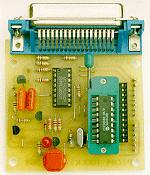
![]() PIC16x84 Toolkit - EPE's original design for PIC16C84 and PIC16F84 microcontrollers. Stand-alone or interface to the PIC Tutor board, the PIC Toolkit was designed for speed and versatility. At last, TASM and MPASM compatibility! The EPE PIC Toolkit is a programmer, program disassembler and bi-lingual translator all in one - a great idea for PIC users everywhere! Translate between TASM and MPASM using easy DOS-based options. You need a PC-compatible computer with QBasic or QuickBASIC installed, and a parallel port. A 12-14V d.c. power supply is also required, which can be derived from an expansion socket or separately.
PIC16x84 Toolkit - EPE's original design for PIC16C84 and PIC16F84 microcontrollers. Stand-alone or interface to the PIC Tutor board, the PIC Toolkit was designed for speed and versatility. At last, TASM and MPASM compatibility! The EPE PIC Toolkit is a programmer, program disassembler and bi-lingual translator all in one - a great idea for PIC users everywhere! Translate between TASM and MPASM using easy DOS-based options. You need a PC-compatible computer with QBasic or QuickBASIC installed, and a parallel port. A 12-14V d.c. power supply is also required, which can be derived from an expansion socket or separately.
![]() The original PIC Toolkit is now obsolete and you should use the TK3 (Toolkit Mk3) - October 2001 issue.
The original PIC Toolkit is now obsolete and you should use the TK3 (Toolkit Mk3) - October 2001 issue.
![]() Greenhouse Computer (Part 1)
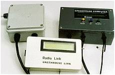
Greenhouse Computer (Part 1)
- microcontroller design uses Atmel's AT89C2051. Monitors and controls heating and watering for your glasshouse. Part 2 includes a radio link, which uses DTI-approved 418MHz radio modules.
![]() In the January 1999 issue (P. 34), we said that under certain circumstances a small d.c. voltage can occur across the probes which may affect the readings. To avoid the problem, amend the Controller p.c.b. as follows: change C14 to 10nF, C13 to 470nF (0µ47), add a 100k resistor in parallel with the probes across TB3. Add a 470nF (0µ47) capacitor in series with TB3 pin 2 and its probe. The software (diskette/ FTP site) has been updated to reduce the default watering time.
In the January 1999 issue (P. 34), we said that under certain circumstances a small d.c. voltage can occur across the probes which may affect the readings. To avoid the problem, amend the Controller p.c.b. as follows: change C14 to 10nF, C13 to 470nF (0µ47), add a 100k resistor in parallel with the probes across TB3. Add a 470nF (0µ47) capacitor in series with TB3 pin 2 and its probe. The software (diskette/ FTP site) has been updated to reduce the default watering time.
Using the L200CV voltage regulator - Andy Flind outlines basic principles of this versatile device.
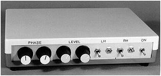
Robert Penfold's novel anti-phasing design will, with a reasonably high quality set of headphones and microphones, provide a reasonable degree of attenuation over the low-mid audio spectrum. Stripboard design.
![]() Low Battery Indicator
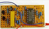
Low Battery Indicator
- high performance, micropower circuit won't load your projects unduly. Compact design fits most d.c. projects. Easy stripboard project