
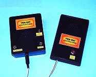
Our ultra-high sensitivity magnetic anomaly detector is just the thing for a bit of UFO-spotting! This device measures the tiniest variation in magnetic field changes, by monitoring the movement of a magnetic compass needle assembly. The article also describes the assembly of a motorised 24-hour event recorder which rotates and provides a chart printout of any detected events, to give hard-copy evidence of the presence of magnetic field changes.
The circuit is highly sensitive, and features a built-in audio alarm together with very low battery power consumption. You can place your UFO Detector overnight and collect the results next day. Full constructional details of every aspect of this interesting device are provided in our consrtructional article. You need to build it... because they're out there!
A "Top Tenner" project which can be constructed for less than £10 ($14 US). This project uses an MEL12 phototransistor to form a flexible and adaptable circuit capable of reacting to "light events". You'll learn about basic electronics too, when you construct our budget-priced project.
![]() Special feature - using PICS and Keypads
Special feature - using PICS and Keypads
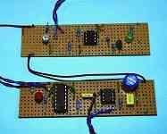
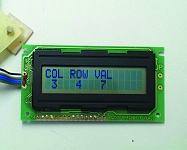
EPE's own Technical Editor explains how to interface PIC microcontrollers to matrixed keypad switches. Software monitoring routines are included, along with details for outputing values to a typical liquid crystal display.
![]()
We haven't featured an intercom project for many years so it's time to present this useful 2-Way communicator which will find a use in any home or office. You'll learn some basic principles of audio electronics into the bargain, by building our battery powered design. Includes p.c.b. details for ease of assembly. An ideal project for electronic hobbyists everywhere.
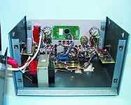
![]() PIC-Monitored Dual PSU (Part 2)
PIC-Monitored Dual PSU (Part 2)
Concluding with the constructional details and setting up routines for our PIC-monitored power supply.
![]() In November 2001 issue (P. 799) we published a correction as follows: Page 890, Fig. 10 should be amended as follows: Link 24 to A11 (not A9); Link 25 to A12 (not A5); Link 26 to A5 (not A12) and Link 27 to A9 (not A11). Note that having the links incorrectly connected as above will not damage the PIC. Ignore the statement saying B14 no connection. Resistors R43 to R46 should read R35 to R38 (10k).
In November 2001 issue (P. 799) we published a correction as follows: Page 890, Fig. 10 should be amended as follows: Link 24 to A11 (not A9); Link 25 to A12 (not A5); Link 26 to A5 (not A12) and Link 27 to A9 (not A11). Note that having the links incorrectly connected as above will not damage the PIC. Ignore the statement saying B14 no connection. Resistors R43 to R46 should read R35 to R38 (10k).
Also in this issue Circuit Surgery explains the operation of Voltage Multiplier circuits - not as simple as they look! Practically Speaking, our practical column for project builders, illustrates component polarity aspects and Ingenuity Unlimited shows off more readers' circuit design ideas. The Schmitt Trigger (Part 3) Precision Triggers and Multivibrators - our in-depth series continues with an analysis of methods for controlling Schmitt threshold values, followed by a look at multivibrator techniques using the Schmitt trigger function.